Autel Maxisys Ultra: Technical Use of Oscilloscope and
Signal Generator Features
The increasing complexity of electronic systems in modern
vehicles has amplified the need for accurate and comprehensive diagnostic
tools. Autel Maxisys Ultra transcends the role of a simple diagnostic scanner,
offering advanced oscilloscope and signal generator features to simplify
vehicle system analysis and diagnostics. This article delves into the technical
applications and advantages of these features.
Oscilloscope Feature and Usage
An oscilloscope is a tool used to visualize electrical
signals. The 4-channel oscilloscope of the Autel Maxisys Ultra enables the
analysis of complex signals and detailed measurements.
Primary Applications:
- Sensor
Diagnostics:
- Analyze
voltage fluctuations from vehicle sensors to verify proper operation.
- For
example, examine the signal waveform of a crankshaft position sensor to
identify synchronization issues.
- Ignition
System Analysis:
- Analyze
the outputs of ignition coils to diagnose potential combustion issues.
- Quick
Troubleshooting:
- Locate
faulty components in complex electrical circuits quickly.
Steps for Use:
- Launch
the Oscilloscope Module:
Select the oscilloscope application from the device software. - Connect
the Probes:
Attach the appropriate probe to the component being tested and select the correct channel. - Adjust
Measurement Parameters:
Set parameters such as voltage range and time base according to the type of signal being analyzed. - Analyze
Live Data:
Examine the signal characteristics through the displayed graphs.
Signal Generator Feature and Usage
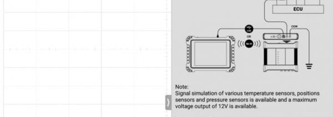
A signal generator creates test signals of specific
frequencies and waveforms (e.g., square, sine, or triangular waves). This
feature is especially useful for simulating and testing component
functionality.
Primary Applications:
- ECU
and Module Testing:
Verify ECU response to input signals to ensure proper operation. - Circuit
Validation:
Test vehicle circuits using simulated signals to verify their response. - Actuator
Control:
Send signals to activate components like injectors or fan motors.
Steps for Use:
- Launch
the Signal Generator Module:
Select the signal generator module from the device menu. - Set
Output Type:
Choose from square, sine, or triangular waveforms. - Adjust
Parameters:
Set frequency, voltage, and waveform according to the component being tested. - Conduct
the Test:
Deliver the generated signal to the test circuit or component and observe the response.
Advantages of These Features
- Time
Efficiency: Speeds up the diagnostic process.
- Comprehensive
Analysis: Facilitates in-depth examination of vehicle systems.
- User-Friendly
Interface: The straightforward software is ideal for both experts and
beginners.
Conclusion
The oscilloscope and signal generator features of the Autel
Maxisys Ultra revolutionize professional vehicle maintenance and repair. These
tools enable detailed and reliable analyses, from electrical fault detection to
circuit simulations.
Discover the power of technology in vehicle diagnostics with
Autel Maxisys Ultra!
Practical Example: Crankshaft Position Sensor Testing
Scenario:
The vehicle exhibits irregular vibration during engine
operation, and the Malfunction Indicator Light (MIL) is on. A diagnostic scan
reveals the P0335 - Crankshaft Position Sensor Malfunction code. However, it
remains unclear whether the issue lies with the sensor, wiring, or ECU (Engine
Control Unit).
1. Testing the Crankshaft Position Sensor with an
Oscilloscope:
A crankshaft position sensor detects the position of
rotating engine parts and controls engine timing. If functioning correctly, it
should generate a voltage signal in waveform format.
Steps:
- Step
1: Prepare the Oscilloscope Module
- Launch
the oscilloscope module on the Autel Maxisys Ultra.
- Connect
the probe cables to the sensor’s signal output and vehicle chassis.
- Step
2: Set Parameters
- Set
the voltage range to 0–5V (commonly used by crankshaft sensors).
- Configure
the time base to 10ms/div to match engine RPM.
- Step
3: Analyze Live Data
- Start
the engine and observe the live signal from the sensor.
- A
healthy sensor typically produces a consistent square or sine wave.
Analysis:
- A
regular waveform indicates the sensor is functional.
- If
no signal is observed, the sensor may be faulty, or there could be wiring
issues.
2. Testing the ECU with a Signal Generator:
If the sensor or its signal cannot be verified, testing the
ECU's response to a simulated signal is necessary.
Steps:
- Step
1: Prepare the Signal Generator
- Connect
the signal generator to the crankshaft sensor’s signal wire.
- Set
voltage and frequency parameters, e.g.,:
- Waveform:
Square
- Frequency:
50 Hz (suitable for idle engine speed)
- Voltage:
0–5V
- Step
2: Start Signal Production
- Send
the simulated signal to the ECU.
- Step
3: Verify ECU Response
- Use
a diagnostic tool to observe engine RPM.
- If
the ECU detects and responds to the simulated signal, the issue lies in
the sensor or wiring. If not, the ECU may be defective.
Outcome:
With the Autel Maxisys Ultra, you can:
- Confirm
whether the crankshaft position sensor is functional.
- Verify
ECU response to simulated signals, pinpointing the root cause of the
issue.
These comprehensive analyses prevent unnecessary part
replacements and expedite the troubleshooting process.


